The stakes are high. EPRI documented $1.4 billion in lost utility revenue from turbine blade failures between 1970 and 1981 alone — and modern replacement costs make that figure look conservative. Most unplanned shutdowns trace back to vibration problems that were detectable weeks or months before the failure event.
This article covers the four primary causes of steam turbine vibration, what happens when those causes go unaddressed, and a practical framework for prevention through alignment, bearing maintenance, thermal management, and continuous monitoring.
Key Takeaways
- Rotor imbalance, shaft misalignment, rotor bowing, and fluid instabilities are the four root causes of most steam turbine vibration problems
- Each cause produces a distinct frequency signature — 1X for imbalance, 2X for misalignment, 0.40–0.45X for oil whirl
- Unaddressed vibration progresses from seal rubs to blade damage, bearing failure, and rotor cracking
- Prevention combines precision alignment, proactive bearing care, thermal management, and continuous vibration monitoring
- Trend tracking against baseline data is the foundation of predictive — not reactive — maintenance
Common Causes of Steam Turbine Vibrations
Steam turbine vibration is the oscillatory motion of rotating and stationary components when mechanical or thermal forces exceed the system's damping capacity. Nearly every case traces back to one or more identifiable root causes, not random degradation.
One critical point: vibration frequency patterns are diagnostic tools. API 684 identifies distinct spectral signatures for each fault type, which makes accurate measurement essential before any corrective action begins.
Rotor Imbalance
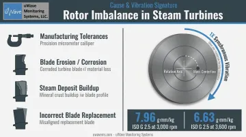
Imbalance occurs when mass distribution across the rotor is unequal, shifting the mass centerline away from the rotation axis. The result is a rotating centrifugal force that appears as synchronous radial vibration at 1X running speed.
Common triggers include:
- Manufacturing tolerances in new rotors
- Gradual mass loss from blade erosion or corrosion
- Steam deposit buildup that adds asymmetric mass
- Incorrect blade replacement where even small weight differences matter
ISO 21940-11 (successor to ISO 1940-1) assigns steam turbines a balance grade of G 2.5, which corresponds to a permissible specific residual unbalance of 7.96 g-mm/kg at 3,000 rpm and 6.63 g-mm/kg at 3,600 rpm. Tighter grades apply only when the OEM or purchase specification explicitly requires them.
Shaft and Component Misalignment
Misalignment between coupled shafts, between a shaft and its bearings, or between the rotor and casing bores generates both radial and axial vibration. The characteristic spectral signature is elevated energy at 2X rpm, though API 684 confirms that misalignment also produces components at 1X and 4X. This means 2X alone is not conclusive without supporting phase and shaft centerline data.
Typical triggers:
- Differential thermal growth during startup and shutdown cycles
- Inadequate re-alignment after maintenance overhauls
- Foundation settling or grouting deterioration over time
- Large steam piping connections applying uncompensated loads to the casing
Rotor Bending and Thermal Stress
Rotor bending is a distinct failure mode from misalignment, triggered by thermal conditions rather than mechanical setup. When a hot rotor rests stationary during shutdown, gravity and residual heat cause it to sag, creating a shaft bow that produces elevated 1X vibration at the next startup. The escalation mechanism is what makes it dangerous:
- Bow causes contact between the rotor and stationary parts (labyrinth seals, diaphragm glands)
- Friction at the contact point generates localized heat
- Localized heat increases the bow
- Increased bow worsens contact
Left unchecked, this cycle can drive the shaft beyond its yield strength — requiring rotor replacement rather than repair. There is no universally applicable shaft bow threshold: acceptable limits depend on the specific turbine model and OEM startup inhibit criteria.
Fluid-Induced Instabilities and Resonance
Three instability modes account for most sub-synchronous failures:
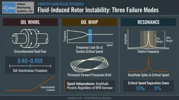
- Oil whirl: The shaft entrains bearing fluid in a circumferential flow, producing sub-synchronous vibration at 0.40–0.45X running speed (per API 684). Amplitude can escalate rapidly, making this one of the more dangerous modes.
- Oil whip: Whirl frequency locks onto a rotor natural frequency. The subsynchronous orbit then persists even as operating speed changes.
- Resonance: A separate issue with its own margin requirements. API 684 requires critical speeds to be separated from maximum continuous speed by at least 15% when the amplification factor falls between 2.5 and 3.55, and by at least 5% below minimum operating speed. When those margins are violated through wear, modifications, or design errors, amplitude spikes sharply at that frequency.
What Happens If Steam Turbine Vibration Is Ignored
Neglected vibration follows a predictable escalation path:
| Stage | Damage |
|---|---|
| Early | Seal and blade tip rubs, minor surface wear |
| Intermediate | Bearing surface degradation, increased steam leakage |
| Advanced | Rotor cracking, blade fatigue damage |
| Catastrophic | Blade loss, rotor failure, unplanned shutdown |
Each stage compounds repair costs and outage duration. Beyond mechanical damage, excessive vibration reduces turbine efficiency through steam leakage past damaged seals and aerodynamic losses from rubbed blades — and creates serious safety risks for personnel working near the equipment.
Warning Signs You're About to Have a Vibration Problem
Vibration failures rarely arrive without warning. These three signals typically precede serious damage and warrant immediate investigation:
Amplitude or frequency shift: A sudden or progressive increase in overall vibration amplitude at bearing housings, or the appearance of a new sub-synchronous component near 0.5X rpm that cannot be explained by a known load or speed change.
Sensory indicators: Unusual heat at bearing housings, audible changes (grinding, knocking, high-pitched tones), or vibration felt through the turbine deck or connected piping — all suggesting contact between rotating and stationary parts.
Shaft centerline drift: Eccentricity shift detected by proximity probes, rising bearing temperature, or changes in axial thrust position. Per ISO 7919-2, a magnitude change of 25% of the B/C zone boundary is significant — even if total vibration remains within Zone B. For a 3,000 rpm turbine, the Zone B/C boundary sits at 165 µm peak-to-peak (relative).
How to Prevent Steam Turbine Vibrations
Preventing steam turbine vibrations means addressing root causes before they develop — through disciplined engineering practices applied at installation, during maintenance outages, and in daily operations. Four areas drive the majority of preventable vibration events: alignment, bearing condition, thermal management, and continuous monitoring.
Precision Alignment and Rotor Balancing
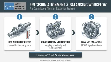
- Perform precision shaft alignment at every major maintenance outage, using hot alignment checks — not just cold targets — to account for actual thermal growth during operation
- Verify coupling eccentricity and rotor concentricity with casing bores
- Conduct dynamic balancing of the rotor assembly after any blade replacement or component change, targeting at minimum ISO G 2.5 grade unless OEM specifications require tighter tolerances
Correct alignment eliminates the uneven radial and axial load distribution that produces 2X misalignment vibration and excessive bearing preloads. Proper balancing eliminates the 1X imbalance force. Together, they address the two most statistically frequent vibration causes.
Proper Bearing Maintenance and Lubrication
- Inspect journal and thrust bearings on a scheduled basis for babbitt wear
- Verify bearing clearances fall within OEM specifications after every reassembly (clearances are bearing-geometry, journal-diameter, and speed-specific — no universal value applies)
- Maintain correct lubrication viscosity and flow rates for the operating temperature range
Adequate oil film damping suppresses fluid whirl and reduces the rotor's sensitivity to imbalance forces. An ASME case study confirmed that changes in lube-oil temperature and supply pressure can trigger subsynchronous 1/2X onset — demonstrating how film properties affect rotordynamic stability. Worn bearings allow eccentricity changes that destabilize the rotor and invite seal rubs.
Controlled Thermal Management During Startup and Shutdown
- Follow OEM-specified turning gear procedures after every shutdown, keeping the rotor slowly rotating until the high-pressure cylinder reaches the OEM's recommended cooldown temperature
- EPRI guidance recommends at least 4 hours of pre-start turning for most major turbine OEMs, and approximately 5 hours per week during extended outages
- Monitor casing temperature gradients and control steam admission rates during hot starts to avoid thermal shock
Controlled rotation prevents the gravitational rotor bow that causes rub-induced 1X vibration at the next startup. Managing casing temperature differentials prevents casing distortion that shifts bearing alignment and tightens internal clearances — both of which amplify vibration risk.
Continuous Vibration Monitoring
Monitoring hardware and alert thresholds are what make the three practices above actionable at scale:
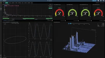
- Install proximity probes at bearing locations in X-Y orientation (45° and 135° from vertical, per API 670) to measure shaft displacement amplitude, frequency, and phase simultaneously
- Establish baseline vibration signatures immediately after commissioning or a major overhaul
- Set alert and danger thresholds based on ISO zone tables and OEM limits — for a 3,000 rpm turbine, ISO 7919-2 places the Zone A/B boundary at 80 µm peak-to-peak (relative) and the Zone C/D boundary at 260 µm
- Implement 24/7 data capture with automated alerts so deviations are caught immediately during off-hours or remote operations
Continuous monitoring converts vibration management from reactive to predictive. Trends in amplitude, phase shifts, and frequency components give advance warning of imbalance growth, bearing wear, or fluid instability — often weeks before the condition reaches a destructive level.
Tips for Long-Term Prevention and Control
Sustained vibration control requires discipline beyond individual maintenance tasks:
Baseline readings — Document amplitude, frequency, and phase for each bearing location immediately after commissioning or a major overhaul. Trend this data across operating cycles to catch gradual degradation before it reaches alarm thresholds.
Operator training — Teach operators to recognize a new frequency component or an unusual amplitude trend, and know when to escalate. That capability is as valuable as any sensor system.
Inspection logs — After every outage, record blade condition, bearing and seal clearances, alignment data, and rotor eccentricity readings. Patterns across multiple outage cycles often predict recurring issues that a single inspection would miss.
Remote monitoring — Cloud-hosted platforms with real-time data and automated threshold alerts let maintenance teams track turbine health across multiple units without constant on-site presence, including weekends, off-shifts, and extended remote operations.
Conclusion
Steam turbine vibrations are not random events. Every cause — rotor imbalance, shaft misalignment, thermal bowing, fluid instabilities — produces a recognizable spectral pattern that points directly at the corrective action required.
The cost comparison is clear. Proactive measures cost a fraction of what a major rotor failure or extended unplanned outage demands:
- Precision alignment and periodic bearing maintenance
- Controlled startup and thermal stabilization procedures
- Continuous vibration monitoring with defined alert thresholds
A structured vibration management program is the most economical long-term strategy for any facility running steam turbines.
Frequently Asked Questions
What is turbine vibration?
Turbine vibration is the oscillatory motion of rotating and stationary turbine components caused by mechanical or thermal forces that exceed the system's damping capacity. Low-level vibration is normal; elevated or changing vibration signals an underlying mechanical problem that requires investigation.
Why do turbines sway?
Turbines exhibit excessive motion due to imbalances, misalignment, resonance, or fluid instabilities in the rotating assembly. These forces shift the rotor off its intended axis and transfer oscillatory energy into the turbine structure, foundation, and connected piping.
What are the three types of vibration in turbines?
Three main types appear in steam turbines:
- Transient vibration — momentary oscillation, typically during startup or shutdown
- Forced vibration — sustained oscillation driven by imbalance, misalignment, or blade passage forces
- Self-excited (fluid-induced) vibration — sub-synchronous instability from bearing or seal fluid interaction
What are the most common causes of steam turbine vibration?
The four primary causes are rotor imbalance, shaft misalignment, rotor bending from thermal stress, and fluid-induced instabilities or resonance. In practice, most problems involve more than one of these acting together.
How do you detect steam turbine vibration early?
Early detection relies on three core tools:
- Proximity probes measuring shaft displacement at each bearing
- Continuous trending of amplitude, frequency, and phase
- Automated alerts that flag deviations from baselines before damage occurs
What happens if steam turbine vibration is left unchecked?
Unchecked vibration escalates from seal and blade tip rubs to bearing surface failure, rotor cracking, and potentially catastrophic blade or rotor loss.