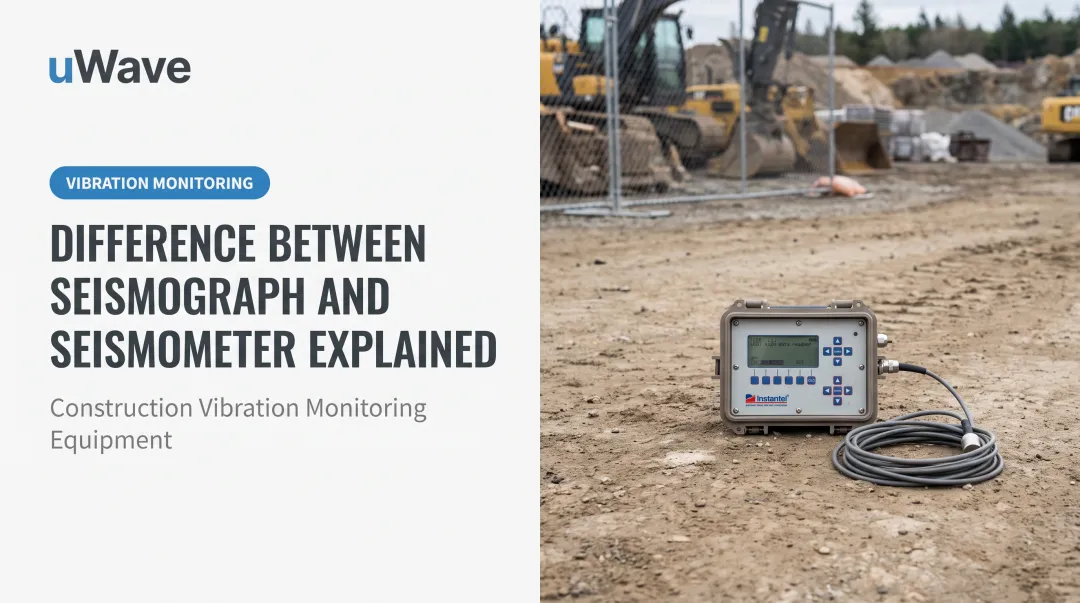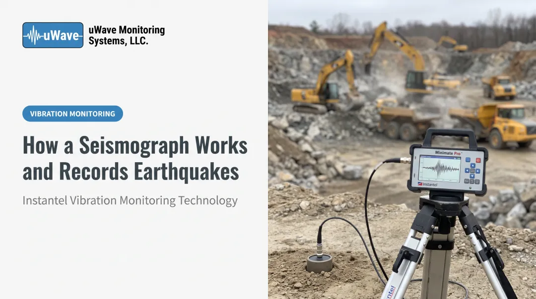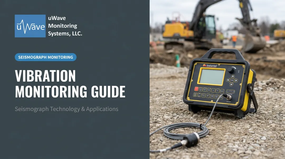
Used across construction monitoring, oil and gas exploration, earthquake research, and mining, geophones are the workhorses of ground vibration measurement. This guide covers everything you need to know: how geophones work, their key components, the different types available, real-world applications, and how they compare to other sensor technologies.
Key Takeaways
- Geophones are passive electromagnetic sensors that convert ground movement into an electrical voltage signal
- Output voltage is proportional to ground velocity — not displacement or acceleration — setting them apart from accelerometers and seismometers
- Applications span seismic exploration, blast monitoring, structural health checks, and water leak detection
- Geophone arrays improve subsurface imaging by capturing seismic wavefronts from multiple points simultaneously
- In construction and blast monitoring, Peak Particle Velocity (PPV) is the key measurement geophones provide — and the figure regulators require
What Is a Seismic Geophone?
A seismic geophone is a passive electromechanical sensor that detects ground movement caused by seismic waves and converts that motion into an electrical voltage signal for recording and analysis. The name comes from the Greek roots ge (earth) and phone (sound) — essentially, a device that listens to the earth.
The critical distinction: geophones measure ground velocity, not displacement or acceleration. The electrical voltage they output is proportional to how fast the ground is moving at the sensor's location, which makes them well-suited for detecting the dynamic motion produced by blasts, pile driving, and natural seismic events.
According to the SEG Wiki definition, a geophone transforms seismic energy into electrical voltage. SLB's glossary is more specific: it detects ground velocity produced by seismic waves and converts it into electrical impulses.
As Dean and Grant noted in 2024, the geophone remains the original and still most common sensor used for land seismic surveys. Decades of field reliability, low cost, and ruggedness compared to more sensitive instruments have kept it the dominant choice.
That velocity-sensing capability comes with a directional constraint worth understanding:
- A single geophone detects motion along one axis only
- Capturing full three-dimensional ground motion requires three mutually orthogonal geophones
- This 3-component (3C) configuration is standard in construction monitoring seismographs, including those from Instantel
How Does a Seismic Geophone Work?
The Electromagnetic Induction Principle
The core mechanism uses a coil of wire suspended by springs inside the field of a permanent magnet. When the ground vibrates, the geophone case — along with the magnet — moves with it. The coil, held in place by its own inertia, remains relatively stationary. This relative movement between the coil and magnet generates a voltage through electromagnetic induction.
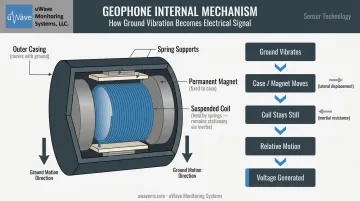
The faster the relative motion, the higher the output voltage. This is why geophones output a velocity signal — one that seismographs can directly amplify and record.
Natural Frequency and Sensitivity
Every geophone has a natural (resonant) frequency — the point at which it is most sensitive to ground motion. Common natural frequencies include:
- 4.5 Hz — recommended for MASW (surface wave analysis) and deeper investigation depths, per the Kansas Geological Survey
- 10 Hz — the most widely used frequency for land seismic exploration
- 28–100 Hz — used for shallow surveys and construction vibration monitoring
Sensitivity specifications vary by model. Two common examples:
| Model | Natural Frequency | Sensitivity |
|---|---|---|
| Geospace GS-ONE LF | 4.5 Hz | 100.4 V/m/s |
| Sercel SG-10HS | 10 Hz | 85.8 V/m/s |
There is no single universal sensitivity value — always check the manufacturer datasheet for your specific model.
Damping and Spurious Frequency
Two additional parameters shape geophone performance:
- Damping: A resistor placed across the geophone terminals flattens the sharp resonance peak. An undamped geophone spikes sharply at its natural frequency; proper damping produces a smoother, more usable response curve.
- Spurious frequency: The resonant frequency perpendicular to the intended measurement direction — this sets the practical upper frequency limit. A 10 Hz geophone (such as the Sercel SG-10HS) typically reaches ≥250 Hz, while a 4.5 Hz model may cap around 120 Hz.
The resulting voltage signal is small. A seismograph or data acquisition unit receives it, then amplifies, digitizes, and records it for analysis.
Types of Seismic Geophones
Vertical vs. Horizontal Geophones
Vertical geophones measure up-down ground motion and are by far the most common type. Standard land seismic surveys typically deploy one vertical geophone per receiver location.
Horizontal geophones detect lateral ground motion in a single direction — making them essential for distinguishing P-waves from S-waves in shear-wave seismic surveys. The Sercel SGH-10, for example, is a 10 Hz horizontal model with a sensitivity of 22.8 V/m/s.
Frequency Variants
| Natural Frequency | Typical Use Case |
|---|---|
| 2–4.5 Hz | Passive seismic, deep MASW surveys |
| 5–10 Hz | Land exploration, earthquake monitoring |
| 10–28 Hz | Refraction surveys, general construction monitoring |
| 100 Hz | Shallow surveys, near-field blast monitoring |
Natural frequency determines what a geophone can "hear." Lower frequencies capture slower, deeper seismic events, while higher frequencies prioritize near-surface resolution — useful for blast monitoring and shallow surveys.
3-Component (3C) Geophones
Three geophones packaged in a single unit — oriented along the X, Y, and Z axes — enable full three-dimensional ground motion capture. This triaxial configuration is standard in professional construction monitoring seismographs.
The Instantel Micromate Plus, Micromate, and Minimate Pro units used by uWave Monitoring Systems all incorporate 3C geophones with two sensor standard options:
- ISEE-standard sensors: 2–250 Hz
- DIN-standard sensors: 1–315 Hz
Applications of Seismic Geophones in the Field
Seismic Exploration (Oil, Gas, and Minerals)
In land seismic surveys, controlled sources — explosives or vibroseis trucks — generate waves that travel through the subsurface and reflect off geological boundaries. Geophones record those reflections, and the resulting data is processed to produce subsurface images used to identify hydrocarbon reservoirs and mineral deposits. The geophone remains the dominant sensor for this work, though modern nodal recording systems are changing how individual sensor data is captured and processed.
Earthquake and Seismic Hazard Monitoring
Networks of geophones deployed across wide areas record natural seismic events in real time. A 2014 study at Mount St. Helens deployed 904 geophones within 15 km of the summit crater, each using a 10 Hz element recording at 250 samples per second — demonstrating the scale of dense temporary geophone deployments used in active seismic research.
Construction and Blast Vibration Monitoring
This is the application most relevant to contractors, project managers, and site operators.
Geophones measure Peak Particle Velocity (PPV) generated by blasting, pile driving, excavation, and heavy equipment near existing structures. Those measurements are compared against regulatory thresholds to confirm compliance and protect adjacent buildings.
Governing standards include:
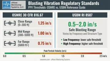
- OSMRE 30 CFR 816.67: Maximum PPV limits of 1.25, 1.00, and 0.75 in/s depending on distance from the protected structure
- USBM RI 8507: Safe blasting levels ranging from 0.5 to 2.0 in/s depending on frequency and structure type
For multi-day or remote projects, manual data retrieval creates gaps in compliance documentation. uWave Monitoring Systems addresses this with Field-to-Cloud remote monitoring stations — solar-powered enclosures with cellular modems that automatically push event data to the uWave Project Manager platform.
Project teams receive automated email and SMS alerts the moment vibration thresholds are exceeded, with no one required on site.
Water Leak Detection
Geophones also detect acoustic vibrations transmitted through soil and pipe walls from pressurized underground leaks. Utilities use this technique to pinpoint leaks without excavation — cutting both downtime and dig costs. U.S. utilities lose an estimated 6 billion gallons per day to leaking pipes, making this one of the more cost-justified applications of geophone technology in municipal infrastructure.
What Is a Seismic Geophone Array?
A geophone array — sometimes called a geophone string — is a network of multiple geophones connected across a survey area to capture seismic data from multiple points simultaneously. More sensors mean better spatial coverage and cleaner data.
Wiring Configurations and Trade-Offs
How you wire the array changes its electrical behavior:
- Series connection: Higher output voltage, but higher impedance — which increases susceptibility to electrical and static noise
- Parallel connection: Lower impedance, but reduced output voltage
- Series-parallel combination: The standard compromise, balancing output and impedance for practical field use
Wiring choice affects more than signal strength — it also determines how well your array handles noise. By averaging signals across multiple sensors, arrays suppress coherent noise, particularly ground roll, which is one of the most common interference sources in land seismic surveys. CREWES research confirms that acquisition-stage stack arrays attenuate ground roll effectively, though spatial aliasing limits how far simple geometric filters can go.
Modern Nodal Systems
Fixed-geometry arrays are now routinely paired with — and sometimes replaced by — nodal recording systems. These autonomous units (like ZLand or INOVA Quantum nodes) include an internal geophone, onboard data storage, and in some cases GPS and wireless communication. Instead of depending on analog array geometry to handle noise, nodal systems record individual sensor data digitally. That means noise suppression happens in post-processing, giving survey teams far more control over the final dataset without committing to a fixed field geometry upfront.
Geophone vs. Seismometer vs. Accelerometer
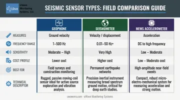
The right sensor comes down to your frequency range, site conditions, and what you're actually trying to measure. Here's how the three main types stack up:
| Feature | Geophone | Seismometer | Accelerometer (MEMS) |
|---|---|---|---|
| Measures | Ground velocity | Ground velocity/displacement | Ground acceleration |
| Typical frequency band | 1–500 Hz (model-dependent) | 0.01–50 Hz and beyond | DC to high frequency |
| Sensitivity | Moderate–high (model-specific) | Very high | Varies |
| Cost | Lower | Higher | Low–moderate |
| Best use case | Field surveys, construction monitoring | Permanent earthquake networks | High-amplitude, near-field events |
| Form factor | Compact, rugged | Larger, sensitive | Solid-state, compact |
Practical selection guidance:
- Geophones are the go-to for construction vibration monitoring, geotechnical investigations, and large-area seismic surveys — robust, cost-effective, and well-matched to the 2–250 Hz range where most construction events register
- Seismometers are preferred when detecting very small or distant events at very low frequencies, typically in permanent monitoring network applications
- MEMS accelerometers excel in compact nodal systems, high-amplitude near-field recordings, and applications where tilt tolerance matters
That said, the lines between these sensor types are blurring in practice. Modern nodal systems now routinely pair geophone elements with onboard GPS, digital storage, and wireless communication — which means field crews can often get broadcast-quality data from a device that fits in a backpack. For construction and infrastructure monitoring specifically, this shift has made it easier to deploy dense sensor arrays without the cost or complexity of traditional seismometer networks.
Frequently Asked Questions
What is a seismic geophone?
A seismic geophone is a passive sensor that converts ground velocity caused by seismic waves into an electrical voltage signal. It operates through electromagnetic induction and is used across seismic exploration, construction blast monitoring, and earthquake research. It measures velocity — not displacement or acceleration.
What is a seismic geophone array?
A geophone array is a network of multiple geophones connected in series, parallel, or a series-parallel combination, deployed across a survey area to capture seismic data from multiple points at once. Arrays improve subsurface imaging resolution and can suppress coherent noise like ground roll through signal averaging.
How much does a seismic geophone cost?
Exploration-grade geophone elements from manufacturers like Sercel or Geospace vary considerably by specification and channel count. Complete monitoring systems — including seismographs, sensors, and data acquisition hardware — represent a larger investment. uWave Monitoring Systems offers factory-certified used Instantel seismographs from roughly $3,000 to $7,000, with rental options available for project-based needs.
What is the difference between a geophone and a seismometer?
Geophones are passive, cost-effective velocity sensors operating roughly in the 1–500 Hz range, best suited for field surveys and construction monitoring. Seismometers are more sensitive broadband instruments — capable of detecting signals below 0.01 Hz — used in permanent earthquake monitoring networks where detecting distant or very small events is the priority.
What is Peak Particle Velocity (PPV) and why does it matter?
PPV is the maximum speed at which a particle of ground moves during a vibration event such as a blast or pile drive, measured in mm/s or in/s. PPV is the standard metric in construction and mining for determining whether ground vibrations could damage nearby structures or exceed regulatory limits set by standards like OSMRE 30 CFR 816.67 and USBM RI 8507.