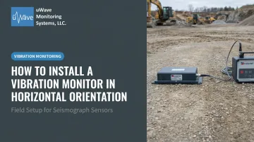
Field technicians at construction, mining, blasting, and transit sites perform most of these installations. A specialist is not required, but the installer must understand axis orientation and surface coupling requirements before they touch a single bolt. Models like the Instantel Micromate, Micromate Plus, Minimate Plus, and Blastmate III are common at these sites, each using an external triaxial geophone connected via cable.
When installation goes wrong, the consequences are specific: an unlevel unit introduces cross-contamination between axes; poor surface coupling attenuates signal strength; a misaligned transducer may underreport PPV from the actual vibration direction. All three failures produce misleading data — and misleading data creates compliance exposure.
Key Takeaways
- Use bolting with a leveling plate on hard surfaces; sandbagging is only acceptable at very low vibration levels
- Confirm level with the integrated bubble level both before and after final bolt tightening
- Orient the transducer's X-axis (longitudinal axis) toward the vibration source
- Run a Sensorcheck (or equivalent sensor test) on all axes before starting any monitoring session
- Document every installation: location, surface type, transducer orientation, configuration settings, and photographs
Prerequisites and Safety Considerations
Two checks must happen before any installation begins: surface type and sensor configuration. Getting either wrong affects data accuracy for the entire monitoring period.
Confirm Surface Type and Attachment Method
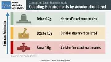
Surface type determines your attachment approach. The ISEE Field Practice Guidelines for Blasting Seismographs establish clear coupling thresholds:
- Below 0.2 g acceleration: No burial or attachment required, but firm contact is still necessary
- 0.2 g to 1.0 g: Burial or attachment is preferred
- Above 1.0 g: Burial or firm attachment is required
On hard surfaces — concrete, bedrock, compacted base — bolting, clamping, or adhering is the correct method. On soft or earthen ground, burial or staking is required; flat placement without anchoring will compromise your data.
Segarra et al. found that free-placed and sandbagged mounts on rock produced accurate horizontal ground motion readings only below 15 Hz at tested vibration levels of 5 and 20 mm/s. Anchoring and plastering outperformed all other methods across the frequency range studied.
Verify Sensor Configuration
All Instantel models in uWave Monitoring Systems' rental and sales inventory — Micromate, Micromate Plus, Minimate Pro, Minimate Plus, Blastmate III — use an external triaxial geophone connected via cable; none have a fully internal geophone.
Before going to site:
- Inspect the geophone cable along its full length for cuts, kinks, or damaged connectors
- Confirm the geo spikes are present and undamaged
- Check that the leveling plate or fastening plate is compatible with your specific model
Non-Negotiables Before You Start
Do not proceed if any of the following conditions exist:
- The surface is actively vibrating (wait for a full work stoppage before placing the geophone)
- Standing water is present or submersion is possible
- The surface is loose, crumbling, or unable to provide firm plate contact
- Site safety clearances — blast radius, machinery exclusion zones, pedestrian paths — have not been confirmed
Tools and Materials Required
Hardware requirements vary slightly by model. Instantel's High Frequency Triaxial Geophone (used with Minimate Pro4 and Pro6) requires a 9.5 mm (3/8-inch) bolt or threaded rod. The standard Micromate geophone uses a 6.4 mm (1/4-inch) bolt, with the rod extending at least 65 mm (2.5 inches) above the surface.
Essential items for hard-surface horizontal installation:
- Leveling plate or fastening plate (model-appropriate)
- Anchor bolt or threaded rod (correct diameter for your geophone model)
- Flat washers and lock washers
- Drill with appropriate masonry or concrete bit
- Wrench or spanner
- Triaxial geophone with cable
- Bubble level (if not integrated into the leveling plate)
Recommended additions:
- Cable tie-downs or ground stakes for cable management
- Camera or phone for post-installation documentation
- Protective enclosure for long-duration or remote deployments
One item that doesn't belong on either list above is a sandbag. Some references mention it as an alternative, and the ISEE does specify a sandbag of approximately 4.5 kg (10 lb) of sand with a low, wide profile for maximum ground contact. That said, Instantel's documentation confirms sandbagging is only acceptable at low vibration velocity levels and when direct bolting is impractical — not a general-purpose substitute for bolted installation.
How to Install a Vibration Monitor Horizontally (Step-by-Step)
Horizontal installation follows a fixed sequence. Skipping leveling or surface preparation consistently produces unreliable data that fails engineering review and regulatory scrutiny. On a hard surface with the right tools, expect the process to take 20–40 minutes.
Step 1 — Select and Prepare the Installation Surface
Position the monitor at the designated monitoring point. The surface must be:
- Hard (rock, concrete, or compacted base)
- Free of loose material, standing water, and debris
- Flat enough for the leveling plate to achieve full contact
Use the leveling plate as a template and mark bolt hole locations before drilling. For soft or earthen surfaces, a burial or staking method is required. Horizontal surface installation on soft ground without anchoring is not acceptable.
Step 2 — Attach the Leveling Plate and Drill the Anchor Point
Attach the leveling plate to the monitor using the provided screws, hand-tight only at this stage. Drill the marked hole(s) and install the anchor bolt or threaded rod per the hardware instructions. Do not final-tighten the plate screws yet; the unit still needs positional adjustment.
Step 3 — Position, Orient, and Rough-Secure the Monitor
Slide the monitor and leveling plate over the installed bolt. Add the flat washer and lock washer. Before tightening:
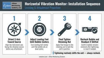
- Orient the transducer's X-axis (longitudinal axis) toward the vibration source. The arrow on top of the geophone must point toward the vibration source — this is explicit in Instantel's Micromate documentation.
- Per ISEE guidelines, the longitudinal/radial channel should point toward the blast site or nearest blast hole.
Tighten the retaining nut enough to hold position, but leave it adjustable for leveling.
Step 4 — Level the Unit and Finalize Attachment
An unlevel unit skews all three channels and can invalidate the recording. Use the leveling feet on the plate and the integrated bubble level to center the bubble in both horizontal directions.
Once the bubble is centered:
- Complete final tightening of the retaining nut
- Recheck the bubble — physical tightening often shifts the unit slightly
- Readjust leveling feet if needed before connecting the cable
Connect the geophone cable to the monitor's GEO port. Ensure the connector is fully seated and the locking collar is secure.
Step 5 — Configure and Prepare for Monitoring
Before starting monitor mode:
- Enter the setup menu and confirm trigger levels, record modes, and project settings
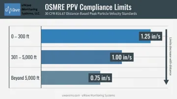
- Match settings to applicable compliance standards. For example, OSMRE limits under 30 CFR 816.67 set the following PPV limits for protected structures:
- 1.25 in/s at 0–300 ft
- 1.00 in/s at 301–5,000 ft
- 0.75 in/s beyond 5,000 ft
- Confirm battery charge is sufficient, or connect external power
Post-Installation Checks and Validation
Tightening hardware is only the start. Run through these three checks before leaving the installation site.
Recheck the Bubble Level
Physical tightening of the retaining nut routinely shifts the unit a few degrees. After all connectors and nuts are fully torqued, look at the bubble level again. If it has moved off-center, loosen the nut, readjust the leveling feet, and re-tighten — skipping this step means an unchecked alignment error carries into the recording.
Run the Sensor Test
On Instantel units:
- Micromate and Micromate Plus: Press the dedicated Sensor Check button. A passing result clears the function; failures appear as specific channel messages
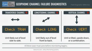
- Minimate Plus and Blastmate III: Press the Test button. A failing axis displays "Check GEO," "Check TRAN," or "Check VERT" on the LCD
Instantel's documentation specifies what each failure means:
- Transverse channel failure → unit is likely out of level side-to-side
- Longitudinal channel failure → unit is likely out of level front-to-back
- Vertical channel failure → unit is tilted, upside down, or a combination
Do not begin monitoring until all three axes pass. Note that a sensor test is not a substitute for annual calibration — it confirms orientation only.
Secure the Cable
Route the geophone cable so it cannot be disturbed by site traffic, wind, or nearby equipment. A cable pulled taut at the connector can physically shift the transducer during a monitoring event and invalidate the recording. Use cable tie-downs or stakes where foot traffic or machinery is present.
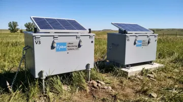
For long-duration or remote deployments, a protective enclosure reduces the risk of accidental disturbance considerably. uWave Monitoring Systems' V3 and V5 enclosures are built for semi-permanent outdoor installation, with solar power, cellular connectivity, and ground anchoring included.
Both units accommodate Micromate, Minimate Pro, Blastmate III, and Minimate Plus instruments — making them a practical option when a deployment needs to run unattended for weeks or months.
Common Installation Problems and Fixes
If something isn't right after installation, it's almost always one of three problems. Use this section to diagnose and correct the issue before re-running your Sensorcheck or adjusting site records.
The three most common issues:
- Monitor out of level after tightening
- Sensor test failure on one or more axes
- Incorrect axis orientation toward the vibration source
Monitor Is Not Level After Tightening
Problem: The bubble is off-center once the retaining nut is fully tightened.
Likely cause: Leveling feet were not adjusted before final tightening, or loose grit, paint chips, or an uneven surface prevents full plate contact.
Fix: Loosen the nut, adjust leveling feet incrementally, and recheck before re-tightening. If the surface is uneven, use a chisel or grinder to flatten the contact area, or move the unit to a better location.
Sensor Test Failure on One or More Axes
Problem: The Sensorcheck returns a failure on one or more geophone channels.
Likely cause: Loose or partially inserted cable connector; cable pinched under the unit during installation; or the transducer was dropped or forced into position.
Fix: Disconnect the cable, reseat the connector firmly until the locking collar clicks, and inspect the cable for kinks or damage. If failure persists after reseating, swap in a known-good cable or transducer to determine which component is faulty — then contact your equipment provider for a replacement or calibration check before returning the unit to service.
Incorrect Axis Orientation Toward the Vibration Source
Problem: After installation, the transducer X-axis is not oriented toward the vibration source.
Likely cause: Orientation was not confirmed before tightening, or the blast or source direction changed from the original plan.
Fix: Loosen the retaining nut, rotate the unit to the correct orientation, re-level, and re-tighten. Update site records and photographs to reflect the corrected position.
Pro Tips for Installing a Vibration Monitor Horizontally
Photograph everything before leaving the site. Capture the bubble level position, transducer orientation relative to the source, cable routing, and surrounding landmarks. These photos protect the project record and simplify re-installation if the unit is disturbed.
Standardize orientation across multiple monitoring points. If a project has several units, establish a consistent convention — for example, X-axis always pointing toward the blast zone or always pointing north — and document it in the monitoring plan. Consistency makes comparative analysis faster at reporting time.
Check hardware before installation in cold or wet conditions. Frozen or corroded bolt threads prevent proper torque during tightening. A unit that feels secure after installation in icy conditions may shift after the first vibration event as hardware loosens.
For long-duration or high-risk sites, use a protective enclosure. Sites with vehicle traffic, public access, or extended weather exposure are high-risk for accidental disturbance. uWave Monitoring Systems' V3 and V5 remote monitoring stations are purpose-built for these conditions: each enclosure is lockable and solar-powered, with cellular connectivity and automated vibration, sound, and maintenance alerts via the uWave Project Manager cloud platform.
Conclusion
The quality of a horizontal vibration monitor installation — specifically leveling precision, surface coupling integrity, and transducer orientation — determines whether recorded data is defensible for compliance reporting, structural damage assessment, or regulatory review. A physically secure but improperly leveled or misaligned unit is still a failed installation.
Every deployment should follow the same sequence before you walk away from the site:
- Prepare and clean the mounting surface
- Follow the leveling sequence to spec
- Validate with a sensor test
- Secure and route the cable
- Photograph the final setup for your records
That sequence takes minutes. Skipping steps can mean unusable data, failed compliance reviews, or a full repeat deployment — none of which are recoverable on a tight project schedule.
Frequently Asked Questions
Where should a vibration sensor be placed?
For ground vibration monitoring in construction or blasting contexts, place the sensor at the designated monitoring point closest to the structure or asset being protected. The surface must be firm and level, with the transducer's primary horizontal axis pointed toward the vibration source.
What is the ISO standard for vibration monitoring?
ISO 4866:2010 — Mechanical vibration and shock: Vibration of fixed structures — is the primary international standard for measuring and evaluating vibration effects on buildings. It is commonly used alongside regional standards such as DIN 4150-3:2016 (Germany) and BS 7385-2:1993 (UK).
Can a vibration monitor be installed horizontally on a soft surface?
Soft-surface horizontal installation requires a different approach than hard-surface bolting. The preferred method is burying the geophone into compacted ground or using a sandbag anchor for very low velocity sites.
Does the orientation of a vibration monitor affect measurement accuracy?
Yes. An unlevel unit causes the vertical and horizontal geophone axes to record mixed signals, corrupting both PPV calculations and dominant frequency data. If the horizontal axis is not pointed toward the vibration source, the unit may also underreport the true peak particle velocity from the dominant vibration direction.
How do I verify my vibration monitor is level after installation?
Most ground vibration monitors and their leveling plates include an integrated bubble level. The bubble should be centered within the target ring after all leveling feet are adjusted and the retaining nut is tightened. Always recheck after final tightening — the torque process routinely shifts the unit slightly.
What is the difference between bolting and sandbagging a ground vibration monitor?
Bolting — using a leveling plate and anchor bolts into a hard surface — is the preferred and most reliable method, ensuring firm coupling and accurate data across the full frequency range. Sandbagging (approximately 4.5 kg / 10 lb of sand, low and wide profile) is only appropriate where vibration velocities are expected to remain very low and direct bolting is impractical.